Computer Architecture Approach
: 컴퓨터의 명령어 집합 구조[Instruction Set Architecture, ISA], 프로세서의 명령어 처리 방식으로 CISC와 RISC가 있다.
CISC [Complex Instruction Set Computer]
: 복잡한 명령어 세트를 사용하는 컴퓨터 아키텍쳐로, 하나의 명령어로 여러 단계의 작업을 수행할 수 있도록 설계되었다.
- 유연성 : 다양한 고급 명령어를 통해 복잡한 작업을 단순화할 수 있다.
- 메모리 효율성 : 더 적은 수의 명령어로 작업을 수행할 수 있어 코드 크기가 작을 수 있다.
- 복잡성 증가 : 명령어 세트가 복잡해지면서 CPU 설계와 구현이 어려워진다.
- 많은 클럭 사이클 소요 : 복잡한 명령어 처리는 더 많은 클럭 사이클을 소모할 수 있다.
RISC [Reduced Instruction Set Computer]
: 단순하고 최소한의 명령어 세트를 사용하는 컴퓨터 아키텍쳐로, 각 명령어가 하나의 간단한 작업을 수행하도록 설계되어 있다.
- 고속 실행 : 단순한 명령어가 빠르게 실해오디어 고성능을 발휘할 수 있따.
- 단순성 : CPU 설계가 단순해지고 전력 소모가 줄어든다.
- 코드 크기 증가 : 더 많은 명령어가 필요하여 프로그램의 코드 크기가 커질 수 있다.
- 메모리 사용 증가 : 자주 사용하는 명령어가 반복되어 메모리 사용량이 증가할 수 있다.
Memory Architecture
: 메모리 아키텍처, 프로그램 코드와 데이터의 저장·접근 방식으로 폰 노이만 구조와 하버드 구조가 있다.
폰 노이만 구조 [Neumann Architecture]
: 컴퓨터 시스템의 기본 아키텍쳐로, 존 폰노이만이 제안한 모델이다. 데이터와 프로그램을 동일한 메모리 공가에 저장하는 개념을 도입하였다.

- 단일 메모리 공간 : 데이터와 명령어가 동일한 메모리 공간에 저장된다. 메모리는 주소로 구분되며, 특정 주소의 데이터를 읽거나 쓸 수 있다.
- 프로그램 내장형 컴퓨터 : 프로그램 명령어를 메모리에 저장하고, CPU가 읽어 순차적으로 실행한다.
- CPU [중앙 처리 장치] : ALU, CU, Register가 존재한다.
- Bus System : 주소 버스[메모리 주소 전달], 데이터 버스, 제어 버스가 있다.
폰 노이만 구조의 구성 요소
- 메모리 : 프로그램과 데이터를 저장하며, 주소 지정 방식으로 접근한다.
- 중앙처리장치[CPU] : 메모리에서 명령어와 데이터를 읽어와 처리하며, 명령어 인출[Fetch] → 명령어 해독[Decode] → 명령어 실행[Execute] 순서로 실행한다.
- 입출력 장치[I/O Device] : 외부 장치와 데이터를 교환한다. 키보드, 마우스, 프린트 등이 해당한다.
폰 노이만 구조의 동작 과정
- 명령어 인출 [Fetch] : 프로그램 카운터[PC]에 저장된 주소를 통해 메모리에서 명령어를 가져온다. 가져온 명령어를 명령어 레지스터에 저장하고, 다음 명령어 주소로 증가한다.
- 명령어 해독 [Decode] : 명령어 레지스터에 저장된 명령어를 해독하여 수행할 작업을 결정한다.
- 명령어 실행 [Execute] : 명령어에 따라 ALU를 통해 연산을 수행하거나, 메모리에서 데이터를 읽거나 쓴다. 결과를 레지스터에 저장하거나, 메모리에 기록한다.
폰 노이만 병목 현상
: CPU가 메모리에서 데이터를 읽고 쓰는 동안 다른 작업을 수행할 수 없어 성능 저하가 발생할 수 있는 현상이다.
- 캐시 메모리 : 자주 사용하는 데이터를 고속으로 접근할 수 있는 캐시 메모리에 저장하여 성능을 향상시킨다.
- 파이프라이닝 : 명령어 인출, 해독, 실행 단계를 겹쳐 수행하여 처리 속도를 높인다.
- 하버드 구조 : 프로그램 명령어와 데이터를 분리된 메모리 공간에 저장하여 병목 현상을 줄인다.
폰 노이만 구조의 장단점
Pros)
- 단순성 : 데이터와 프로그램이 동일한 메모리 공간에 있어 설꼐가 단순하다.
- 유연성: 메모리 공간을 유연하게 사용할 수 있다.
Cons)
- 병목 현상 : 데이터와 명령어가 동일한 버스를 통해 전달되어 성능 저하가 발생할 수 있다.
- 메모리 보호의 어려움 : 데이터와 명령어가 동일한 공간에 있어 보안 문제가 발생할 수 있다.
하버드 구조 [Harvard Architecture]
: 컴퓨터 아키텍쳐의 한 종류로, 프로그램 명령어와 데이터를 별도의 메묄 공간에 저장하고, 각기 다른 버스를 사용하여 접근하는 방식이다. 성능 향상과 병목 현상을 줄일 수 있다.
- 분리된 메모리 공간 : 프로그램 명령어와 데이터를 각각 다른 메모리 공간에 저장한다.
- 분리된 버스 : 명령어 버스와 데이터 버스를 별도로 사용하여 메모리에 접근한다. 명령어와 데이터를 동시에 접근할 수 있어 병목 현상을 줄인다.
하버드 구조의 구성 요소
- 프로그램 메모리 : 프로그램 명령어가 저장되는 메모리 공간으로, CPU는 PC를 통해 명령어를 순차적으로 읽는다.
- 데이터 메모리 : 데이터가 저장되는 메모리 공간으로, CPU는 데이터 주소 레지스터를 통해 데이터를 읽고 쓴다.
- 중앙 처리 장치 [CPU] : ALU, CU, Register가 있다.
- Bus System : 명령어 버스와 데이터 버스가 있다.
- 명령어 버스 : 프로그램 메모리 ↔ CPU, 명령어를 전달한다.
- 데이터 버스 : 데이터 메모리 ↔ CPU, 데이터를 전달한다.
하버드 구조의 동작 과정
- 명령어 인출 [Fetch] : PC에 저장된 주소를 통해 프로그램 메모리에서 명령어를 가져오고, 명령어 버스를 통해 명령어를 CPU로 전달한다.
- 명령어 해독 [Decode] : 명령어 레지스터에 저장된 명령어를 해독하여 수행할 작업을 결정한다.
- 명령어 실행 [Execute] : 명령어에 따라 ALU를 통해 연산을 수행하거나, 데이터 메모리에서 데이터를 읽거나 쓴다. 데이터 버스를 통해 데이터를 전달하고, 결과를 레지스터에 저장하거나 메모리에 기록한다.
하버드 구조의 장단점
Pros)
- 동시 접근 : 명령어와 데이터를 동시에 접근할 수 있어 성능이 향상된다.
- 병목 현상 감소 : 분리된 버스를 사용하여 메모리 접근 병목 현상을 줄인다.
- 빠른 데이터 처리 : 명령어와 데이터의 분리로 더 빠른 데이터 처리가 가능하다.
Cons)
- 복잡성 증가 : 두 개의 메모리 공간과 버스를 관리해야하므로 설계가 복잡하다.
- 메모리 낭비 가능성 : 프로그래모가 데이터 메모리의 크기를 동적으로 조절하기 어렵기 때문에 메모리 낭비가 발생할 수 있다.
폰 노이만 구조 vs 하버드 구조
RISC-V
: 개방형 명령어 세트 아키텍처[ISA]로, 간단하고 확장 가능한 아키텍처이다.
오픈 소스로 제공되어 있고, 임베디드 시스템, IoT, 데이터 센서 등에서 사용되고 있다.
- 개방형 아키텍쳐 : 오픈소스로 제공되며, 누구나 무료로 사용할 수 있다. 명령어 세트는 공개되어 있어, 자유롭게 수정 및 배포할 수 있다.
- 단순한 명령어 세트 : 단순하고 최소화된 명령어 세트를 가지고 있어, 설계가 쉽고 효율적이다. 명령어 길이가 고정되어 있어 디코딩이 단순하다.
- 확장성 : 기본 명령어 세트와 다양한 확장 명령어 세트를 제공한다.
- 고성능 및 저전력 : 고성능 연산과 저전력 소비를 동시에 고려한 설계이다.
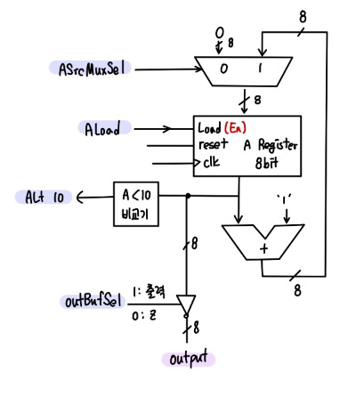
A 변수에 0~9까지 카운트 하는 시스템을 설계.
c언어
A = 0; // 초기화
while (A < 10){
	output = A;
    A = A + 1;
};
halt;
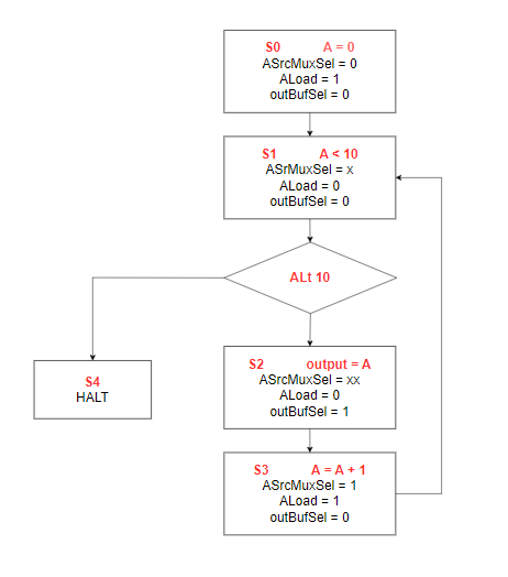
| Instruction | State | ASrcMuxSel | ALoad | OutBufSel |
| A = 0 | S0 | 0 | 1 | 0 |
| A < 10 | S1 | x | 0 | 0 |
| output = A | S2 | x | 0 | 1 |
| A = A + 1 | S3 | 1 | 1 | 0 |
| HALT | S4 | x | 0 | 0 |
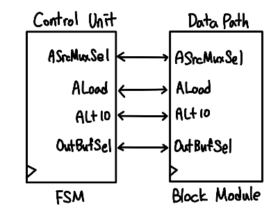
- Dedicated PRocessor : 특정한 작업이나 기능을 수행하도록 설계된 프로세서.
- FPGA에서는 프로그래머블 로직 디바이스로, 사용자가 원하는 기능을 구현할 수 있다. 하드웨어 수준에서 특정 작업을 병렬로 처리할 수 있도록 구성 가능하다.
DataPath.v
`timescale 1ns / 1ps

module DataPath(
    input clk,
    input reset,
    input ASrcMuxSel,
    input ALoad,
    input OutBufSel,
    output ALt10,   // A less than 10
    output [7:0] out
    );

    wire [7:0] w_AdderResult, w_MuxOut, w_ARegOut;

    mux_2x1 U_MUX(
        .sel(ASrcMuxSel),
        .a(8'b0),
        .b(w_AdderResult),
        .y(w_MuxOut)
    );

    register U_A_Reg(
        .clk(clk),
        .reset(reset),
        .load(ALoad),
        .d(w_MuxOut),
        .q(w_ARegOut)
    );

    comparator U_Comp(
        .a(w_ARegOut),
        .b(8'd10),
        .lt(ALt10)
    );

    adder U_Adder(
        .a(w_ARegOut),
        .b(8'b1),
        .y(w_AdderResult)
    );
/*
    outBuf U_OutBuf(
        .en(OutBufSel),
        .a(w_ARegOut),
        .y(out)
    );
*/
    register U_OutReg(
        .clk(clk),
        .reset(reset),
        .load(OutBufSel),
        .d(w_ARegOut),
        .q(out)
    );

endmodule

module mux_2x1 (
    input sel,
    input [7:0] a,
    input [7:0] b,
    output reg [7:0] y
);
    always @(*) begin
        case (sel)
            1'b0: y = a;
            1'b1: y = b;
        endcase
    end

endmodule

module register (
    input clk,
    input reset,
    input load,
    input [7:0] d,
    output[7:0] q
);
    reg [7:0] d_reg, d_next;
    assign q = d_reg;

    always @(posedge clk, posedge reset) begin
        if (reset)  d_reg <= 0;
        else d_reg <= d_next;
    end

    always @(*) begin
        if (load) d_next = d;
        else d_next = d_reg;
    end
endmodule

module comparator (
    input [7:0] a,
    input [7:0] b,
    output lt
);
    assign lt = a < b;  // b: 10 -> 0 ~ 9까지만 가능
endmodule

module adder (
    input [7:0] a,
    input [7:0] b,
    output [7:0] y
);
    assign y = a + b;
endmodule

module outBuf (
    input en,
    input [7:0] a,
    output [7:0] y
);
    assign y = en ? a : 8'bz;
endmodule
ControlUnit
`timescale 1ns / 1ps

module ControlUnit(
    input clk,
    input reset,
    output reg ASrcMuxSel,
    output reg ALoad,
    output reg OutBufSel,
    input ALt10
    );

    localparam S0 = 3'd0, S1 = 3'd1, S2 = 3'd2, S3 = 3'd3, S4 = 3'd4;

    reg [2:0] state, state_next;

    always @(posedge clk , posedge reset) begin
        if (reset) state <= S0;
        else state <= state_next;
    end

    // next state logic
    always @(*) begin
        state_next = state;
        case (state)
            S0: state_next = S1;
            S1: begin
                if (ALt10) state_next = S2;
                else state_next = S0;//S0 : 0~9 반복, S4 : end at 9
            end
            S2: state_next = S3;
            S3: state_next = S1;
            S4: state_next = S4;
            default: state_next = S1;
        endcase
    end

    // output logic
    always @(*) begin
        ASrcMuxSel = 1'b0;
        ALoad      = 1'b0;
        OutBufSel  = 1'b0;
        case (state)
            S0: begin
                ASrcMuxSel = 1'b0;
                ALoad      = 1'b1;
                OutBufSel  = 1'b0;
            end
            S1: begin
                ASrcMuxSel = 1'b1;
                ALoad      = 1'b0;
                OutBufSel  = 1'b0;
            end
            S2: begin
                ASrcMuxSel = 1'b1;
                ALoad      = 1'b0;
                OutBufSel  = 1'b1;
            end
            S3: begin
                ASrcMuxSel = 1'b1;
                ALoad      = 1'b1;
                OutBufSel  = 1'b0;
            end
            S4: begin
                ASrcMuxSel = 1'b1;
                ALoad      = 1'b0;
                OutBufSel  = 1'b0;
            end
            default: begin
                ASrcMuxSel = 1'b1;
                ALoad      = 1'b0;
                OutBufSel  = 1'b0;
            end
        endcase
    end

endmodule
DedicatedProcessor
`timescale 1ns / 1ps

module DedicatedProcessor(
    input clk,
    input reset,
    output [7:0] out,
    output [ 7:0] fndFont,
    output [ 3:0] fndCom
    );

    wire w_ASrcMuxSel, w_ALoad, w_OutBufSel, w_ALt10;
    reg r_clk;
    reg [31:0] counter;
    wire [7:0] w_out;

    assign out = w_out;

    always @(posedge clk, posedge reset) begin
        if (reset) begin
            counter <= 0;
        end
        else begin
            if (counter == 10_000_000 - 1) begin   // 0.1hz, simulation -> 5-1
                counter <= 0;
                r_clk <= 1'b1;
            end
            else begin
                counter <= counter + 1;
                r_clk <= 1'b0;
            end
        end
    end

    ControlUnit U_CU(
        .clk(r_clk),
        .reset(reset),
        .ASrcMuxSel(w_ASrcMuxSel),
        .ALoad(w_ALoad),
        .OutBufSel(w_OutBufSel),
        .ALt10(w_ALt10)
    );

    DataPath U_DP(
        .clk(r_clk),
        .reset(reset),
        .ASrcMuxSel(w_ASrcMuxSel),
        .ALoad(w_ALoad),
        .OutBufSel(w_OutBufSel),
        .ALt10(w_ALt10),   // A less than 10
        .out(w_out)
    );

    fndController  U_fndController(
        .clk(r_clk),
        .reset(reset),
        .digit({6'd0, w_out}),
        .fndFont(fndFont),
        .fndCom(fndCom)
    );

endmodule
fndController.v
`timescale 1ns / 1ps

module fndController (
    input         clk,
    input         reset,
    input  [13:0] digit,
    output [ 7:0] fndFont,
    output [ 3:0] fndCom
    );

    wire [3:0] w_digit_1, w_digit_10, w_digit_100, w_digit_1000;
    wire [3:0] w_digit;
    wire [1:0] w_count;
    wire w_clk_1khz;

    clkDiv #(.MAX_COUNT(100_000)) U_ClkDiv( // (100_000)이 없으면 default
        .clk(clk),
        .reset(reset),
        .o_clk(w_clk_1khz)
    );

    counter #(.MAX_COUNT(4)) U_Counter_2bit(
        .clk(w_clk_1khz),
        .reset(reset),
        .count(w_count)
    );

    Decoder U_Decoder_2x4 (
        .x(w_count),
        .y(fndCom)
    );

    digitSplitter U_DigitSplitter (
        .i_digit(digit),
        .o_digit_1(w_digit_1),
        .o_digit_10(w_digit_10),
        .o_digit_100(w_digit_100),
        .o_digit_1000(w_digit_1000)
    );

    Mux U_Mux (
        .sel(w_count),
        .x0 (w_digit_1),
        .x1 (w_digit_10),
        .x2 (w_digit_100),
        .x3 (w_digit_1000),
        .y  (w_digit)
    );

    BCDtoSEG U_BcdToSeg0 (
        .bcd(w_digit),
        .seg(fndFont)
    );

endmodule


module Decoder (
    input      [1:0] x,
    output reg [3:0] y
);

    always @(x) begin
        case (x)
            2'h0: y = 4'b1110;
            2'h1: y = 4'b1101;
            2'h2: y = 4'b1011;
            2'h3: y = 4'b0111;
            default: y = 4'b1110;
        endcase
    end

endmodule

module digitSplitter (
    input  [13:0] i_digit,
    output [ 3:0] o_digit_1,
    output [ 3:0] o_digit_10,
    output [ 3:0] o_digit_100,
    output [ 3:0] o_digit_1000
);

    assign o_digit_1 = i_digit % 10;
    assign o_digit_10 = i_digit / 10 % 6;
    assign o_digit_100 = i_digit / 60 % 10;
    assign o_digit_1000 = i_digit / 600 % 6;

endmodule

module Mux (
    input      [1:0] sel,
    input      [3:0] x0,
    input      [3:0] x1,
    input      [3:0] x2,
    input      [3:0] x3,
    output reg [3:0] y
);

    always @(sel, x0, x1, x2, x3) begin
        case (sel)
            2'b00:   y = x0;
            2'b01:   y = x1;
            2'b10:   y = x2;
            2'b11:   y = x3;
            default: y = x0;
        endcase
    end

endmodule

module BCDtoSEG (
    input      [3:0] bcd,
    output reg [7:0] seg
);

    always @(bcd) begin  // bcd 변화가 감지되면 실행
        case (bcd)
            4'h0: seg = 8'hc0;
            4'h1: seg = 8'hf9;
            4'h2: seg = 8'ha4;
            4'h3: seg = 8'hb0;
            4'h4: seg = 8'h99;
            4'h5: seg = 8'h92;
            4'h6: seg = 8'h82;
            4'h7: seg = 8'hf8;
            4'h8: seg = 8'h80;
            4'h9: seg = 8'h90;
            4'ha: seg = 8'h88;
            4'hb: seg = 8'h83;
            4'hc: seg = 8'hc6;
            4'hd: seg = 8'ha1;
            4'he: seg = 8'h86;
            4'hf: seg = 8'h8e;
            default: seg = 8'hff;
        endcase
    end

endmodule

module counter #(parameter MAX_COUNT = 4)(
    input  clk,
    input reset,
    output [$clog2(MAX_COUNT)-1:0]  count
);

    reg [$clog2(MAX_COUNT)-1:0] counter = 0;
    assign count = counter; // wire은 assign으로 연결해야함.

    always @(posedge clk, posedge reset) begin  // 비동기 reset
        if (reset == 1'b1) begin
            counter <= 0;
        end
        else begin
            if (counter == MAX_COUNT - 1) begin
                counter <= 0;
            end
            else begin
                counter <= counter + 1;
            end
        end
    end

endmodule

module clkDiv #(parameter MAX_COUNT = 100)(
    input clk,
    input reset,
    output o_clk
);
    reg [$clog2(MAX_COUNT)-1:0] counter = 0;  // [16:0]으로 만들어줌. $clog2 : log2()
    reg r_tick = 0 ;

    assign o_clk = r_tick;

    always @(posedge clk, posedge reset) begin
        if (reset) begin
            counter <= 0;
        end
        else begin
            if (counter == (MAX_COUNT - 1)) begin
                counter <= 0;
                r_tick <= 1'b1;
            end
            else begin
                counter <= counter + 1;
                r_tick <= 1'b0;
            end
        end
    end

endmodule
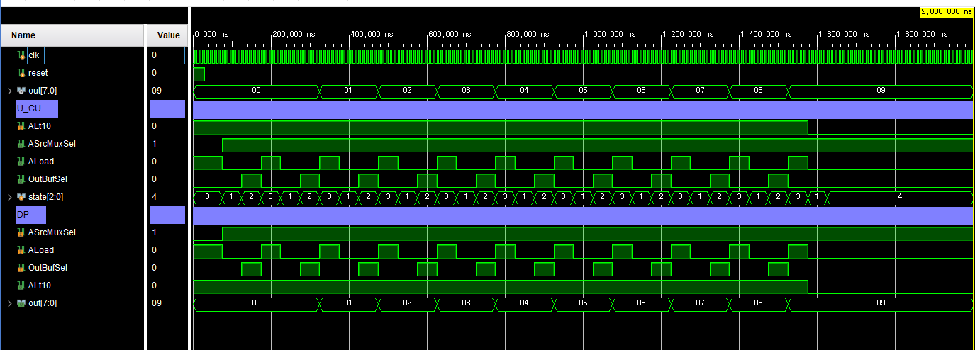
tb_DedicatedProcessor.v
`timescale 1ns / 1ps

module tb_DedicatedProcessor();

    reg clk;
    reg reset;
    wire [7:0] out;

    DedicatedProcessor dut(
        .clk(clk),
        .reset(reset),
        .out(out)
    );

    always #5 clk = ~clk;

    initial begin
        clk = 0;
        reset = 1;

        #30 reset = 0;
    end


endmodule
simulation
로 변경)
constraint
video
'[하만]세미콘 아카데미 > verilog' 카테고리의 다른 글
| 0529 DedicatedProcessor RegisterFile | 2024.07.09 |
|---|---|
| 0528 Dedicated Process num55 | 2024.07.09 |
| 0525 uart tx rx systemverilog | 2024.07.09 |
| 0524 uart fifo | 2024.07.09 |
| 0523 FIFO Systemverilog verification | 2024.07.09 |